http://www.cnczone.com/forums/uccnc-control-software/321726-cnc.html
Aşağıdaki PWM ile ilgili yazı yukarıdaki sayfadan alınmıştır.
-------------------------------------------------------------------------------------------------------------------------
Reply from CNC Drive
The PWM frequency has nothing to do with the base frequency of the motor.
What the UCCNC output is a PWM signal which is a signal changing between logic 0 and 1 in cycles.
The length of one cycle is t=1/f, so for example for a 400Hz frequency it is 0.0025seconds.
The duty cycle means the % of how much part of the cycle the signal is logic 1. The rest of the cycle is logic 0.
For example a 50% duty cycle means that for half of the cycle the signal is logic 1. and for the rest 50% it is logic 0.
How your VFD controls your motor is a totally different thing. The VFD inputs the PWM signal from the UCCNC and the VFD understands this signal as the control lead signal,
usually a breakout board is used which low-pass filters this signal, so the signal will be no more PWM, but an analog signal.
For example if the signal has 50% duty cycle and it has 0V and 5V logic low and high levels then a 50% duty cycle signal low pass filtered will be a 2.5Volts analog signal.
Also in breakout boards this signal is often isolated and the amplitude is changed, gained from 0-5Volts to 0-10Volts, however some VFDs has options to accept 0-5V signals also,
but 0-10V is the more common, the industry standard.
Also most VFDs themselves low-pass filters the analog input signal, so the PWM coming from the UCCNC is read by the VFD as an analog signal, because the VFD has the low-pas RC filter, so then no need to low-pass filter the signal to get an analog input voltage.
So, the VFD is setup to accept this signal from the UCCNC and then it controls the motor based on the analog input signal level.
How the VFD runs the motor can be setup in the VFD with parameters, like with what base frequency the VFD will drive the motor,
but this PWM has nothing to do with the PWM of the UCCNC, this is a totally different thing!
And no, the UCCNC does not vary the PWM signal frequency, you setup the frequency of the PWM signal and it will have always that frequncy, with any S words programmed,
what varies is the duty cycle of the PWM with the different S words.
The UCCNC scales the min. and max. S range to the min. and max. PWM value range, so the min. S will give the min.PWM duty cycle and the max. S will give the max.PWM duty cycle and the inbetween values will be proportinal in the range.
The higher than S max. will give the max.PWM duty cycle and the lower the S min. will give the min.PWM duty cycle since these are the set limits.
In practice what value you set the PWM frequency in the UCCNC only depends on what your breakout board can handle, because if the BOB isolates the signal with optocoupler that has a bandwidth limit,
so it can't throughput any fast signals, so there is a limit in frequency where the signal will be distort, because the optocoupler can't switch any fast, so it will distort the signal if it is changing too fast.
So, you want to set the PWM freq. lower than that bandwidth limit. Usually a few hundred Hz works, and mostly tens of kiloHertz not works without distortion most optocouplers.
Ofcourse there are so called fast optocouplers in the market, but they are expensive and not really used in commercial breakout boards, because they are an overkill and have a higher price than what is nessessary.
Also if the PWM frequency is set lower means it switching slower, so a longer time constant low-pass filter is required and then the slower the signal will respond to changes.
For example if the PWM frequency is 0.1Hz only then the signal will switch only once per every 10 seconds, to low pass that properly about 100 seconds time constant filter is required and that is way too slow compared to how fast you want to spin up and spin down your spindle, so you don't want to set the PWM freq. too low either.
And yes, VFDs mostly need a digital start input for safety (at least it is configurable), so the analog (PWM) input change itself can't start the motor, the M3 relay can be used as the start signal,
so the motor will only start running if the analog signal is in range for the VFD to start plus it has the active M3 digital input signal.
-------------------------------------------------------------------------------------------------------------------------
Mach3'de set edilen PWM değeri, kullandığımız kartın başadebildiği hıza bağlı, bu da kartın kullandığı optoküplörün max hızından kaynaklanıyor. Eğer çok düşük set edilirse, hız değişiklikleri yeterince hızlı VFD/spindle'a aktarılamayabilir. Çok yüksek set edildiğinde ise optoküplörün iletim hızını aşarak hataya neden olur. Aynı sayfada, Gecko için max 10000 Hz gibi çok yüksek bir değer örnek verilmiş. Bilgi yoksa 200-300 Hz girilip denenebilir diye düşünüyorum.
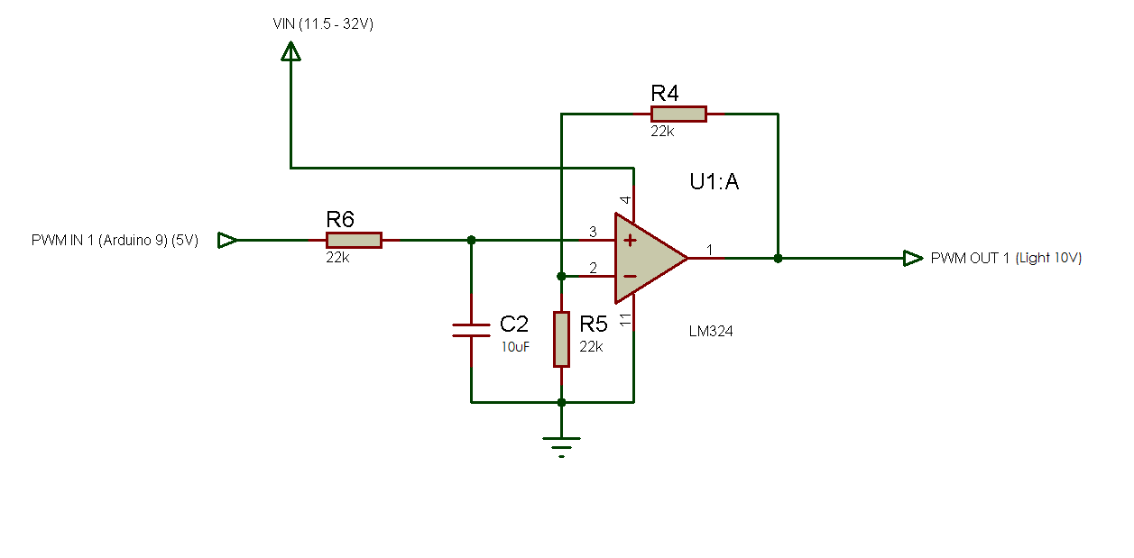
Mesaj #19'daki gibi PWM'i 0-10 volta çeviren ve opto içeren bir devre eklersek, PWM'in hız değeri kullandığımız opto hızından da etkilenecektir.
PWM için, girilen hızın (Hz) veri aktarım kalitesini belirlendiğini ancak spindle'ın hızının kare dalgaların yüzdesi ile belirlendiğini söyleyebiliriz.
@Suat_Korkmaz'ın uyardığı gibi, bahsettiğim PWM hız değeri;
Mach3, Ports & Pins, Spindle Setup, Motor Control,
PWMBase Freq
Mach3 ayarlarını set ederken, bu değerin nasıl belirlendiğini anlayabilmek için epeyce uğraşmıştım.

")